Connection
The WattWächter TTL is a pure IR reading head and requires an external evaluation unit to operate (e.g. ESP32, Raspberry Pi, D1 Mini or Arduino). This page walks you through the initial setup step by step.
For the setup you need:
- An evaluation unit (ESP32, Raspberry Pi, D1 Mini / ESP8266, Arduino, etc.)
- Your own firmware/software to read out the data
- A prepared digital electricity meter (SmartMeter or eHz) with the PIN from your grid operator
Prepare the meter first
Before connecting the WattWächter, your electricity meter must be unlocked (PIN from your grid operator). Follow the Meter Preparation guide to do so.
1. Wiring
Plug the supplied cable into the reading head with its USB-C plug. The four wires at the other end have Dupont connectors that you plug straight onto the pin header of your board:
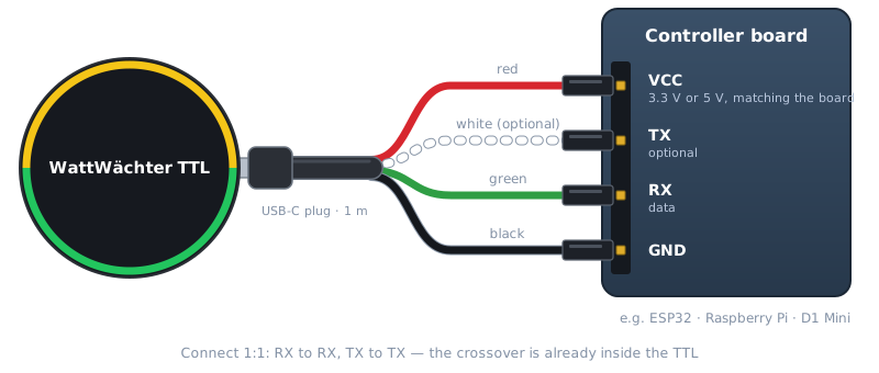
| Wire color | Function on the TTL | Board connection |
|---|---|---|
| Red | VCC (3–5 V) | 3.3 V or 5 V, matching the board |
| Green | RXD (data receive) | RX |
| White | TXD (data transmit) — optional | TX |
| Black | GND | GND |
The USB-C socket is not a USB interface
The socket only carries the supply and the TTL signals. A regular USB cable on a PC, Mac or charger does not work, but nothing gets damaged either. For a direct USB connection there is the WattWächter USB.
Older TTL with a fixed cable
The older head has different wire colors (brown, green, yellow, white), see Older version.
Pins per board
| Wire | ESP32 | Raspberry Pi | D1 Mini (ESP8266) |
|---|---|---|---|
| Red (VCC) | 3V3 |
Pin 1 — 3V3 |
3V3 |
| Green (RXD) | GPIO16 (RX2) |
Pin 10 — GPIO15 / RXD |
RX (GPIO3) |
| White (TXD, optional) | GPIO17 (TX2) |
Pin 8 — GPIO14 / TXD |
TX (GPIO1) |
| Black (GND) | GND |
Pin 6 — GND |
GND |
The guides for ESPHome, Raspberry Pi, Arduino and Python use exactly these pins.
1:1 wiring
The wires are connected 1:1 (RX → RX, TX → TX), as the crossover already takes place inside the reading head. The white TX wire is optional for most meters (only required to send commands to the meter).
Choose the supply to match the board
The WattWächter TTL operates at 3–5 V. Its data line carries the level of the supply voltage: powered with 5 V, it also outputs 5 V on RX. ESP32, ESP8266 and Raspberry Pi only tolerate 3.3 V on their pins — so power the head with 3.3 V on these boards. Then no level shifter is needed. On 5 V boards such as the Arduino Uno, use 5 V. A built-in reverse polarity protection guards the head against incorrect wiring.
ESP32-WROVER
On modules with PSRAM (ESP32-WROVER), GPIO16 and GPIO17 are occupied. Use other free pins there, e.g. GPIO25 (RX) and GPIO26 (TX), and adjust them in the code.
2. Position the reading head on the meter
The WattWächter TTL attaches to the meter with its ring magnet. Place it centered on the optical interface (the metal ring around the two infrared diodes). The cable points upwards.
PIN activation required
For your meter to transmit measurement data via infrared, the extended data display must be enabled on the meter. To do this you need the PIN code from your grid operator. Enter it directly on the meter, then set PIN to Off and Inf to On in the meter menu.
If the green LED (right) flashes regularly, usually every 1–2 seconds, the head is positioned correctly and the meter is sending.
3. Read out the data
Data transmission is serial with a standard baud rate of 9600 baud (SML). Configure the serial interface of your evaluation unit accordingly and parse the received SML telegrams.
Examples with source code can be found under:
- ESPHome: ESP32 to Home Assistant, no code of your own
- Raspberry Pi: set up the interface and check that data arrives
- Arduino and Python: code examples for your own projects
OBIS codes
An overview of the OBIS codes that modern meters provide (tariffs, voltage, current, power, phase angle, device info) can be found under Additional OBIS codes.